
- #Replacing a selenium rectifier with a silicon diode full
- #Replacing a selenium rectifier with a silicon diode series
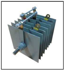
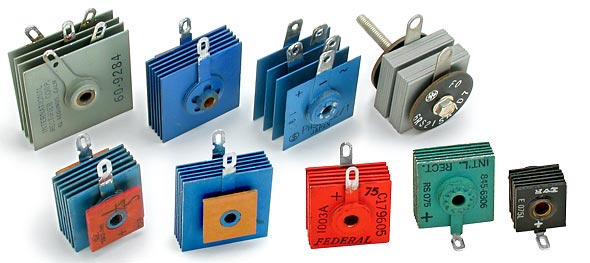
There are basically two types of rectifiers one is the half wave rectifier and the other is the full wave rectifies. On a silicon-controlled rectifier which wire is the anode and which the cathode? Types of rectifier? example:a 12 plate center tapped rectifier 1.5 inches square 12*30=360Vdivide by 2 =180PIV area=2.25 square inches which gives a currentrequirement of a little over one amp so use a 1.5A 200PIV unit. If the voltage is low (under 10VDC) you may need to put asmall valued resistor between the rectifier and capacitor. Replace the electrolitics!!!! If the unit isold enough to have a selenium, they are well past the le 5. You may need toheatsink the new rectifier, especially if the current is over a fewhundred mA. Assume 500mA persquare inch of a single plate's area. Use the maximum of the above and the input electrolitic workingvoltage multiplied by 1.4, then round up to the next standardvoltage within reason (silicon is cheap). If you have documentation, use it, otherwise: rule 1.PIV is 30 volts per plate, divided by the formfactor: rule 1a.Formfactors: diode=1, half bridge (center tap)=2, bridge=4.

For old stereos, etc.you need to estimate the peak reverse voltage and the currentrequirements. If you are working with anultra high voltage stack all bets are off. Spehro Pefhany Spehro Pefhany $endgroup$ Not the answer you're looking for? Browse other questions tagged rectifiersemiconductors or ask your own question. If it has that characteristic horrible (and apparently toxic) rotten garlic/onions smell that Se rectifiers give off when they are dying you can be pretty sure it needs to be replaced. Murphy's law (and Vf voltages) would make the former more likely. Needless to say, if you fiddle with the diodes and don't get it right, you could create charging parameters that damage (or fail to properly charge) a battery. Quite possibly the 2.4 on the Se rectifier stack refers to the current rating, and perhaps 16V is the voltage rating. The nameplate indicates up to a couple amperes, so maybe some 1N5404 3A diodes would work for you.
#Replacing a selenium rectifier with a silicon diode series
Typically Se rectifiers have a forward drop of about 1V per junction, so if there is only one junction or two per diode, then 2 or 3 (respectively) Si diodes in series for each Se diode would be reasonably close. I have a hunch there is something interesting going on there, it may also be saturable to limit the terminal voltage of the charge. The magnetics look like they could be designed to have a very high leakage inductance so it may be kind of a constant current charger. I agree with Olin's comment about maybe needing a series resistor. That looks like a bridge or half bridge rectifier (bridge I would guess).

I figured the electrical system was leaking current somewhere, not understanding it is by design to prevent overcharging.Olin Lathrop Olin Lathrop $endgroup$ $begingroup$ When I pulled the battery for the winter, the charger worked normally. I had it on for days and thought the charger was defective and would only hook it up for a few hours every few days. I started with a fresh battery at the beginning of last years riding season and would put it on the charger in between rides. Although I can't say that for sure as no spec was provided to state how the Abort mode is triggered. It must be very close to the changeover voltage as the charger never went into Abort mode, which is when the charger determines the battery can't be fully charged. If I am reading the Zener testing section correctly in the manual, the diode in proper spec can be bleeding off 2a ranging from 13.5 -15.5 V, and at a lesser rate down to 12.75V when it should be 0a.Īs the specs overlap, a properly operating Zener can bleed off enough current so that this particular charger won't ever charge the battery enough to click over to Maintenance mode. According to its specs the Maximum Charge Voltage is 12-14.8 V. Very Interesting, I'm using a Schumacher SFM-1562A 1.5a Automatic Charger.


 0 kommentar(er)
